Speakers & Amplifiers
Transmission Line speakers
I have been thinking about TL speaker boxes again. These gained some popularity in the 70s after R A Bailey published some practical designs in Wireless World magazine. It has long been recognised that TL speakers have a smooth and extended bass response. The roll-off is 6dB/ oct, whereas for a closed box it is 12dB/ oct (and 24dB/ oct for a bass reflex). Bass transient response is also reported to be good. The main problem (apart from the large size) has been that there has been no way of getting a known result with them, requiring tuning after construction. Now, several research articles have been published that may address this issue. Robert Robinson has done a thesis on the topic, and Martin King has actively researched TL design.
websites:
http://www.quarter-wave.com
http://audio.thesonicboomers.com
http://www.puresound.co.nz
http://www.diyaudio.com/forums/multi-way/13324-how-use-martin-j-kings-software-design-tl-loudspeaker.html
http://www.pmc-speakers.com
http://www.diyaudio.com/forums/multi-way/1839-pros-cons-transmission-line-speakers.html
calculators:
http://www.mh-audio.nl/bailey_tml.asp
http://www.mh-audio.nl/tml.asp
Which way round to mount near field monitors?
I have noticed lately a few pictures of near field monitors positioned with the tweeters on the inside. This is opposite to conventional wisdom, which is to put the woofers on the inside. So, which is right? Well it turns out that there is one right answer but neither of these is it. The correct way to place the speakers is vertically (then you might think we are simply changing the argument to 'which way up does the tweeter go'? This is not the case, as our hearing is biased to the lateral plane. That's not to say you wouldn't consider inverting the boxes depending on the height and angle they are mounted on).
Anyway, if for some reason they must go sideways, there is no right answer. Some manufacturers do suggest the way to put them, but that shouldn't be hard and fast, as every room is different. If the tweeters are placed out then you get a wider stereo image, and a solid 'in the middle' bass. If the tweeters are in then it gives a narrower image, but avoids a possible 'hole in the middle'.
Also of importance is time alignment. All frequencies should travel the same path-length. Some design geometries are pre-adjusted for this, whereas with cheaper speakers it is a case of making it better (or worse) by setting the horizontal angle of the speaker. Since a delay of even 1mS can be audible, it is important to get this right for critical listening.
So, generally it is best to put them vertically. If that is not possible, then experiment to find the best case. And one more thing; always read the manufacturers instructions (for example the Focus SM9 nearfields really are designed to lie flat).
T-S database
An on-line database of Thiele-Small parameters is available here: <http://www.thielesmall.com/database.asp>
Speaker driver action

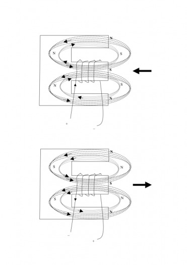
A colleague recently asked my to explain how exactly a dynamic speaker uses the electro-magnetic principle to move the cone. I started to sketch the motor and the lines of force, then thought why not just Google a good picture of the principle instead. And guess what... I couldn't find one. There are lots of simplified drawings and descriptions that say things like " when a current is applied to the voice-coil a corresponding movement occurs...". So I have made my own and here it is.
Description: The permanent magnet creates a constant magnetic field with two flux paths as shown. In fact a driver could work with a single pole in the middle of the voice coil but that would not be very efficient (and even the best moving-coil loudspeakers are very inefficient). The magnetic field is three dimensional and can be considered as lines of flux radiating from the N Pole through the magnet to the S Pole and back across to the N Pole (flux is synonymous with electrical current, so think direction and circuit). Around the coil a second and similar magnetic field is present as long as there is current in the coil. This electromagnet will change in strength and polarity in exact response to the input current. When a positive voltage appears on the inside side of the voice-coil then a N Pole is created at that end of the coil (and an S Pole at the outside). The voice-coil is a lot tighter wound than shown in the drawing, and can be situated closer to one end of the magnet. Thus there will be two adjacent S Poles at the outside of the magnet and these will repel. As the magnet is fixed, the voice-coil must move back into the gap. When the polarity changes (as in the second diagram), the electromagnet polarity (flux direction) is also reversed. This presents an N Pole at the outside of the coil that will now be attracted to the S Pole of the permanent magnet. Hence the voice-coil moves outward.
Description: The permanent magnet creates a constant magnetic field with two flux paths as shown. In fact a driver could work with a single pole in the middle of the voice coil but that would not be very efficient (and even the best moving-coil loudspeakers are very inefficient). The magnetic field is three dimensional and can be considered as lines of flux radiating from the N Pole through the magnet to the S Pole and back across to the N Pole (flux is synonymous with electrical current, so think direction and circuit). Around the coil a second and similar magnetic field is present as long as there is current in the coil. This electromagnet will change in strength and polarity in exact response to the input current. When a positive voltage appears on the inside side of the voice-coil then a N Pole is created at that end of the coil (and an S Pole at the outside). The voice-coil is a lot tighter wound than shown in the drawing, and can be situated closer to one end of the magnet. Thus there will be two adjacent S Poles at the outside of the magnet and these will repel. As the magnet is fixed, the voice-coil must move back into the gap. When the polarity changes (as in the second diagram), the electromagnet polarity (flux direction) is also reversed. This presents an N Pole at the outside of the coil that will now be attracted to the S Pole of the permanent magnet. Hence the voice-coil moves outward.
My first speaker cabinet project

About the time I started High School my parents built a new house, and one of the items purchased for it was a new La Gloria Stereogram. This single piece of furniture included a valve amplifier, an open reel tape recorder, record player, radio tuner (including a short-wave band), and 12" speakers built into each end. I remember being excited by the possibility of hearing the new "stereo" LPs, but they didn't sound much different to mono. The combination of having the speakers placed only 4 1/2' apart, and a L-R separation of about 20dB on the record was the reason. The living room was large (22' long by 13' wide, and 2288 cu'), so at a comfortable listening distance the 'listening triangle' was more like a wedge, so not much stereo was perceptible.
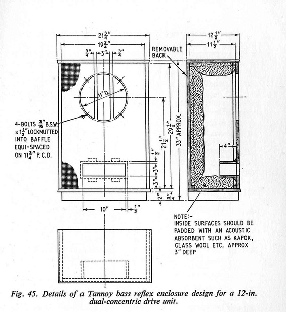
When I was 15, I bought a book named 'Audio' by Clement Brown and in it was this drawing. In the school holidays I made two speaker boxes to this design out of Coreboard. The drivers were the 12" Rola dual cone's taken out of the Stereogram. This was before the days of T-S alignments so it didn't really occur to me that putting a different driver into these boxes might not work too well! In any case they sounded ok to my young ears, and did introduce me to some great stereo. I had them on either side of the room sitting on a large built-in bookshelf which was about 4' off the floor. I stained them orange for extra appeal (hey, it was the 70s!). After high school, I left home, and replaced the Rola drivers in the La Gloria, and took the boxes with me. The drivers I put in were Philips, model AD-5200, from memory.
When I was 15, I bought a book named 'Audio' by Clement Brown and in it was this drawing. In the school holidays I made two speaker boxes to this design out of Coreboard. The drivers were the 12" Rola dual cone's taken out of the Stereogram. This was before the days of T-S alignments so it didn't really occur to me that putting a different driver into these boxes might not work too well! In any case they sounded ok to my young ears, and did introduce me to some great stereo. I had them on either side of the room sitting on a large built-in bookshelf which was about 4' off the floor. I stained them orange for extra appeal (hey, it was the 70s!). After high school, I left home, and replaced the Rola drivers in the La Gloria, and took the boxes with me. The drivers I put in were Philips, model AD-5200, from memory.
Practical Wireless Winton amplifier circuit
I built this amplifier for my home stereo in 1980 and it is still in use. I repaired it once (noise due to a dried out coupling capacitor), and other than that it has never missed a beat (or any other bits of the music it reproduces). You can see the simplicity of the output stage due to it using Power MOSFETS.
| pw_winton-p1.jpg | |
| File Size: | 424 kb |
| File Type: | jpg |
| pw_winton-p2.jpg | |
| File Size: | 385 kb |
| File Type: | jpg |
